
An elegant facade can become expensive before the first panel reaches the cutting table. I see the nesting layout as the point where design decisions meet material purchasing, machine time, and assembly requirements.
Sheet Nesting for Architectural Fabrication arranges flat components on stock sheets while respecting the constraints that make them manufacturable. The goal extends beyond squeezing shapes together: every finished part must retain its dimensions, orientation, finish, and identity.
What Does Sheet Nesting Actually Optimize?
Nesting determines where parts sit, how many sheets a job requires, and what material remains after cutting. Architectural applications include metal cladding, plywood ribs, decorative screens, acrylic inserts, and folded panel blanks.
Manual nesting suits small, simple jobs. Automated nesting evaluates alternative arrangements using defined geometry and constraints. Neither method eliminates the need for fabrication review.
A dense layout can still be expensive if it creates difficult handling, excessive cutting, or unusable remnants. Compare material consumption with production effort rather than judging the layout by appearance alone.
Prepare Architectural Parts Before Nesting

Develop Complete Flat Patterns
Folded components need developed blanks that include returns, hems, fixing features, and bend allowances. Nesting the visible facade outline instead of the complete blank underestimates material requirements.
Confirm model units, quantities, and revision status. Remove duplicate cutting geometry and resolve incomplete boundaries before export. Separate materials, thicknesses, and finishes into compatible production groups.
Material selection also influences how architectural components should be prepared for digital fabrication. Exploring bio-based materials for digital fabrication offers further insight into working with renewable material options and understanding their fabrication requirements. Evaluating material properties, sheet dimensions, and processing constraints before nesting helps ensure that cutting layouts balance resource efficiency with reliable production outcomes.
Preserve Orientation and Part Identity
Record the show face and permitted rotations. Veneered plywood and directional metal finishes may require consistent orientation even when rotation would improve packing.
Give each part type an identifier linked to its quantity and installation destination. Agree where identification belongs so marks remain readable without damaging exposed surfaces. Keep revision information attached to the production package.
Choose a Nesting Method That Matches the Machine
Rectangular and Guillotine Nesting
Rectangular nesting uses part dimensions or bounding boxes. It works well for regular panels but can leave unnecessary space around irregular outlines.
Guillotine layouts follow successive straight cuts across a sheet or remaining section. They suit equipment and workflows requiring that cutting pattern. A freely packed layout may look efficient yet be impractical for a panel saw.
True-Shape Nesting
True-shape nesting uses actual outlines, allowing irregular components to fit around neighboring geometry. Where the process permits, smaller parts can occupy openings within larger blanks.
For Sheet Nesting for Architectural Fabrication, choose the method according to geometry, cutting equipment, and production constraints. Software sophistication matters less than whether the resulting layout can be executed reliably.
Set Cutting Constraints Before Comparing Layouts
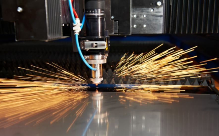
Kerf is the width of material removed by cutting. Part spacing must accommodate the cutting process and any additional requirements for stability or heat management. Do not assume one spacing value works across routers, lasers, and waterjets.
Reserve edge margins for trimming, clamps, or other machine restrictions. Use the usable stock dimensions when testing whether parts fit.
Common-line cutting lets adjacent parts share a cutting path where geometry and the process allow it. Confirm dimensional compensation and fabricator approval before enabling it.
Micro-tabs can retain parts during cutting, but their removal adds work. Place them where finishing marks will not compromise the architectural surface.
Measure Yield Without Hiding Production Costs
Calculate gross material utilization as total finished blank area divided by total purchased sheet area, multiplied by 100.
For an illustrative comparison, 24 square meters of blanks cut from ten sheets measuring 1.2 by 2.5 meters achieve 80% gross utilization. If a verified arrangement accommodates those same blanks on nine sheets, utilization becomes approximately 88.9%.
Area arithmetic alone cannot prove that nine sheets will work. Actual geometry, spacing, edge margins, and orientation must support the arrangement.
Track sheet count, cut length, pierces, handling, and reusable remnants separately. For overlapping cladding, also distinguish blank area from visible coverage; purchased material includes concealed laps and returns.
Beyond improving sheet utilization, computational methods can help identify opportunities to reuse offcuts and incorporate recovered materials into future design projects. Exploring computational design for material reuse offers a broader perspective on how digital tools can support resource-efficient decisions throughout architectural fabrication. By evaluating reusable remnants alongside cutting yield and production costs, fabricators can reduce material waste without compromising component requirements.
Connect the Nest to Finishing and Installation
Compare single-type and mixed-type layouts when compatible parts share stock. Mixed nesting may improve packing, while production sequencing and sorting can change the overall advantage.
For facade projects, efficient nesting must also support the wider manufacturing and assembly process. Understanding digital fabrication of facade panels provides additional context on how coordinated design data, material selection, and fabrication methods influence the production of architectural cladding components. Aligning nesting decisions with these requirements helps ensure that material savings translate into practical manufacturing and installation benefits.
Assess whether leftovers have a realistic future use. A large remnant with an unsuitable finish or thickness should not automatically receive full material value.
Issue the approved layout with part schedules, material specifications, identification rules, and fabrication files. Coordinate finishing batches and packing destinations so efficient cutting does not create confusion during assembly.
Frequently Asked Questions
1. What is Sheet Nesting for Architectural Fabrication?
It is the arrangement of architectural component blanks on sheet stock to control material use while meeting cutting, orientation, and production requirements.
2. Can every part rotate freely?
No. Grain, directional finishes, and fabrication requirements may restrict rotation. Define those restrictions before optimizing.
3. Is the highest utilization always best?
No. Cutting time, stability, sorting, and finishing effort can outweigh a small material saving.
4. When should nesting begin?
Begin while panel geometry remains adjustable. Review the final layout again after design approval and before production release.
Make the Layout Earn Its Place
I would judge a nesting plan by what reaches installation successfully. A useful layout reduces unnecessary purchasing, protects the intended finish, and keeps parts traceable.
Bringing fabrication constraints into design early creates room to improve geometry before changes become expensive. The strongest result is an approved arrangement that the workshop can cut, finish, identify, and deliver confidently.