A curved wall can look effortless until the workshop has to produce it from flat sheets. I approach kerf bending plywood: creating curved architectural surfaces as a balance between geometry, material behavior, and finish quality.
Relief cuts make the panel flexible, but the real challenge is creating a repeatable curve that stays supported and looks continuous. This guide explains how to plan the bend, test the plywood, machine the cuts, and turn a flexible blank into finished architectural joinery.
How Does Kerf Bending Work?
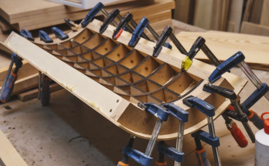
Kerf bending uses closely spaced cuts on one face of a panel while leaving continuous material beneath the opposite face. For a conventional convex surface, the slots sit inside the bend and close as the panel curves.
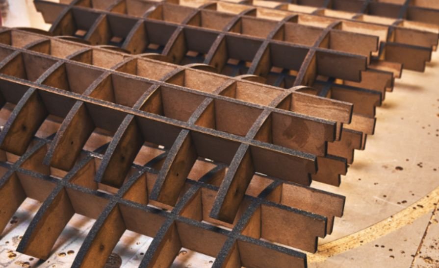
The remaining thin web connects the thicker ribs between cuts. This arrangement reduces bending stiffness, allowing a rigid sheet to follow a former. However, material removal also reduces strength. Curved partitions, reception counters, column wraps, and cabinet fronts usually need backing or framing.
Plan the Curve Before Selecting Cut Settings
Define Radius, Direction, and Visible Faces
Start with the finished radius, panel dimensions, and bend location. Distinguish the inside radius from the outside radius and account for any veneer or facing added later.
Mark which surface remains visible and where seams, edges, and fixings will appear. Straight parallel kerfs suit simple cylindrical curves. Compound curves require a different fabrication strategy or specially developed patterns.
For more complex curved surfaces, parametric design can help coordinate geometric relationships, panel dimensions, and fabrication constraints before production begins.
Exploring parametric design and digital fabrication offers further insight into how adaptable digital models can translate design intent into manufacturable components. This approach is particularly valuable when adjusting radii, repeating patterns, or coordinating multiple parts within a consistent architectural system.
For a reception counter, draw the supporting ribs and panel joints alongside the outer profile. A beautiful radius alone does not explain how the component will assemble.
Coordinating curved architectural elements also requires a reliable connection between the design model and the information used for production. A BIM-to-fabrication workflow helps bridge this gap by aligning component geometry, assembly requirements, and fabrication data before manufacturing begins. Establishing these relationships early can make complex curved joinery easier to coordinate, revise, and produce accurately.
Choose Consistent Plywood
Inspect the panel edge for veneer thickness, core voids, and irregular layers. Consistent construction makes test results more useful; hidden gaps can create local weak points.
Do not select plywood solely by its nominal thickness. Two sheets of similar thickness can behave differently because their veneer arrangements differ.
Inspect the layers that will remain after cutting. A decorative face veneer may run in a different direction from the thicker underlying ply, so surface grain alone can mislead.
How Deep and Far Apart Should Cuts Be?
Test Depth on Production Offcuts
Measure the actual sheet thickness and make trial cuts in material from the same batch. Preserve a continuous web, then test whether it bends gradually around the intended former.
Leaving too much material increases bending resistance. Removing too much can cause splitting or breakage. There is no universally reliable remaining thickness for every plywood construction and radius.
Record the cutter width, depth, spacing, grain orientation, and trial radius. Change one variable at a time so each test explains something useful.
Balance Spacing With Surface Quality
Closer kerfs distribute bending across more locations and can reduce visible faceting. Excessive cutting, however, leaves a fragile blank.
Wider spacing preserves more material but may produce flat segments instead of a smooth arc. An online calculator can estimate a starting pattern, but physical testing must confirm it.
A practical workflow for Kerf Bending Plywood: Creating Curved Architectural Surfaces therefore combines geometric planning with trial bending. Neither a calculator nor a generic spacing chart can fully represent the plywood in your workshop.
Cut, Form, and Secure the Panel
A table saw with suitable indexing can produce repeated cuts for simple components. CNC routing helps when multiple panels require consistent patterns or localized changes in spacing.
Efficiently machining curved plywood components also requires careful planning of how each blank fits onto the available sheet stock.
This is where sheet nesting for architectural fabrication becomes relevant, helping fabricators arrange component profiles to reduce material waste while respecting cutting constraints and part orientation. Coordinating nesting with the kerf pattern and panel dimensions can improve material utilization without compromising the accuracy of the finished curve.
Support the sheet during machining and maintain uniform cut depth. Use appropriate guarding, workholding, and dust extraction for the equipment.
Build a rigid former matching the required profile. Dry-fit the blank before applying adhesive, bending progressively rather than forcing one section sharply. Stop if the face develops cracks or the layers separate.
Use ribs, a backing skin, or a designed frame to retain the shape. Select adhesive for the actual bonding surfaces and follow its application and curing instructions. Filling slots does not automatically restore the original uncut panel strength.
Finish the Surface and Prevent Common Defects
Check the dry-fitted curve under raking light, which reveals facets and small surface irregularities.
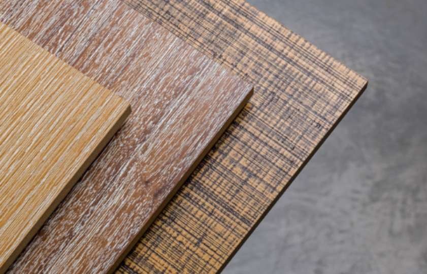
Avoid aggressive sanding of decorative plywood: the face veneer may be thin. Depending on the finish specification, an additional veneer or suitable facing can create a more continuous appearance.
Resolve exposed edges, panel seams, and fixings during the mockup. Inspect the cured assembly before installation, including its radius and attachment positions.
When cracking occurs, revisit the retained layers and bending force. When the curve looks uneven, check cut consistency and former accuracy.
Frequently Asked Questions
1. What Is the Minimum Bend Radius?
There is no universal minimum. Plywood construction, remaining web thickness, cutter width, and spacing all affect the achievable curve. Test the intended material.
2. Can This Technique Produce Load-Bearing Elements?
For Kerf Bending Plywood: Creating Curved Architectural Surfaces, treat ordinary kerfed panels as supported architectural finishes. Load-bearing applications require engineering of the complete assembly.
3. Is Flexible Plywood a Better Choice?
It can suit sweeping decorative curves. Bent lamination may suit applications needing continuous layers and greater stiffness. Compare support requirements, finish, labor, and available materials.
4. Can the Kerfs Remain Visible?
Yes, when intentionally designed as a feature. Consider cleaning, edge quality, exposure, and support before choosing an open pattern.
Making the Curve Work
I would prioritize a tested mockup over an ambitious cutting pattern. Once the material, radius, support, and finish work together, fabrication becomes easier to repeat. Taking time to record successful cut settings also helps maintain consistency across multiple panels and reduces avoidable material waste.
Before installation, I would check the finished curve under the lighting it will actually receive. Small facets, uneven seams, or exposed fixings can become more noticeable once the surface sits beside other architectural finishes. Resolving these details in the workshop is usually easier than correcting them on site.