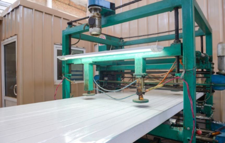
A beautifully curved panel becomes a construction problem when its edges cannot meet the neighboring pieces. That is where I begin evaluating incremental sheet forming for custom architectural metal panels with buildability, rather than appearance alone.
This digital fabrication method shapes flat metal through controlled local deformation, allowing customized surfaces without a dedicated full-shape die for every variation. Its real value depends on matching design freedom with material behavior, production time, and reliable connections.
How Does Incremental Sheet Forming Work?
A rounded tool follows a programmed path across a securely clamped sheet. Repeated passes gradually deform the metal into a three-dimensional surface. Geometry comes from a digital model, while the forming strategy determines how that geometry develops physically.
Unlike stamping, the process can accommodate changing panel shapes without manufacturing a separate matched die for each design. Fixtures, tools, programming, and inspection still require investment.
Single-Point and Double-Sided Forming
Single-point incremental forming uses a forming tool against a sheet held in a fixture. Double-sided configurations add a coordinated opposing tool to support deformation locally. Neither arrangement guarantees perfect accuracy; equipment stiffness, material properties, and toolpath design influence the result.
When Is ISF Suitable for Architectural Cladding?
The strongest candidates involve relatively small production runs, varied geometries, or distinctive relief patterns. Potential applications include customized rainscreens, interior metal surfaces, and experimental lightweight assemblies.
For hundreds of identical components, conventional forming may offer better production economics. A sculptural appearance alone does not justify robotic fabrication when simpler folding or rolling can achieve the intended geometry.
Incremental sheet forming for custom architectural metal panels deserves consideration when variation creates genuine architectural value and the project can accommodate prototyping.
How Do You Move From CAD to a Finished Panel?
Coordinate Geometry and Material Selection
Divide the architectural surface into manageable panels before generating toolpaths. Consider machine reach, fixture size, transport, access for installation, and replacement of individual pieces.
Choose the alloy, temper, and starting thickness with the fabricator. Aluminum, copper, and steel behave differently, and changing temper can alter formability significantly. Avoid applying one successful prototype’s settings to every material.
Preparing accurate digital models is a critical step in translating customized panel geometry into reliable manufacturing instructions.
This is where preparing architectural CAD files for digital fabrication becomes particularly relevant, helping designers organize geometry, verify dimensions, and address potential fabrication constraints before toolpaths are generated.
A well-coordinated CAD workflow can reduce downstream errors and improve communication between the design team and fabricator.
Develop the Fixture and Toolpath Together
Clamping must resist forming forces without allowing unwanted movement. The fixture also needs clearance for the tool, support equipment, and the intended panel depth.
Tool diameter, vertical step-down, lateral spacing, lubrication process, and travel speed affect the process. Smaller increments can improve surface appearance but increase manufacturing time. Establish settings through representative trials rather than assuming universal values.
Digital fabrication methods can also use flexible textile systems to create complex architectural geometries. Digitally knitted concrete formwork explores how programmed knitting can shape formwork for concrete shells, offering a useful comparison of how digital toolpaths, material behavior, and fabrication constraints influence architectural outcomes.
Inspect Before Trimming and Finishing
Compare the formed panel with its target geometry using suitable measurements or scanning. Check attachment zones separately from the decorative surface because their functional tolerances may differ.
Coordinate trimming, holes, edge folds, and finishing with the forming sequence. Maintain panel identification through inspection, packaging, and installation so unique components reach their intended positions.
Which Design Limits Cause the Most Problems?
Thinning, Springback, and Surface Marks
Forming stretches the sheet, producing uneven thickness changes. Steep walls, abrupt transitions, or demanding local geometry can increase the risk of rupture. Springback and residual stress can also move the finished surface away from its digital target.
Toolpaths may leave visible contour marks. Decide whether these belong to the architectural expression or require additional finishing. Evaluate a physical sample under lighting comparable to the finished building.
Edges, Seams, and Connections
Keep decorative forming coordinated with functional borders. Edge distortion can undermine an otherwise successful panel by preventing seam closure or consistent joint spacing.
Reserve attachment zones where appropriate and test adjoining panels together. Coordinate thermal movement, drainage, corrosion compatibility, and the supporting structure. A formed metal surface becomes usable cladding only when its connections and envelope details work.
What Do Architectural Prototypes Reveal?
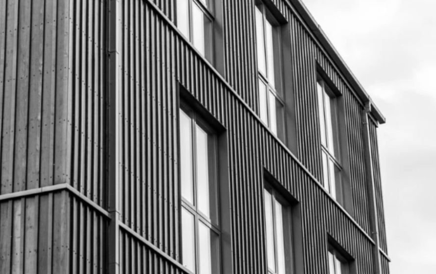
Built research examples demonstrate both opportunities and limitations. Customized aluminum cladding has served as a rainscreen, while formed components have also contributed bracing to experimental structures. Copper façade research has explored standing-seam connections alongside differentiated panel geometry.
Documented cladding trials recorded forming times ranging from minutes to several hours per component, depending on the design. They also revealed warping and localized ruptures. These observations support early mockups and realistic scheduling; they are not universal production benchmarks.
Beyond sheet-based forming, large-scale additive manufacturing in construction demonstrates how digital fabrication can produce building components and architectural forms directly from digital models. Comparing these approaches helps designers assess how material requirements, production methods, geometric complexity, and quality-control procedures influence the feasibility of customized construction systems.
How Should You Evaluate Cost and Quality?
Request quotations that include programming, fixtures, forming, handling, inspection, trimming, finishing, and packaging. Compare the complete installed system with alternative methods, rather than comparing forming costs alone.
Approve a representative mockup containing demanding curvature, an actual joint, and an attachment detail. Record accepted dimensional deviations, appearance, thickness checks, and assembly behavior. Use those criteria to guide production approval.
Frequently Asked Questions
1. Is Incremental Sheet Forming for Custom Architectural Metal Panels economical?
It can be suitable for varied panels and smaller runs. Savings on dedicated dies must outweigh programming, forming time, fixtures, finishing, and inspection.
2. Can formed panels carry structural loads?
Some experimental systems use formed geometry structurally. Each application still requires engineering verification; added relief does not automatically establish load capacity.
3. Does dieless forming eliminate tooling?
No. It reduces dependence on dedicated full-shape dies, but still needs forming tools, secure fixtures, and suitable support equipment.
4. Can the process create smooth double-curved surfaces?
It can form complex surfaces within material and equipment limits. Smoothness depends on toolpaths, geometry, and finishing, so approve a representative sample.
My Final Take
I would choose this method when customized geometry delivers a clear benefit and the fabrication team can prove repeatable results. I would begin with the hardest connection and curvature, then inspect the assembled mockup before approving production. That approach turns an ambitious digital surface into panels that can be manufactured, installed, and maintained reliably.