
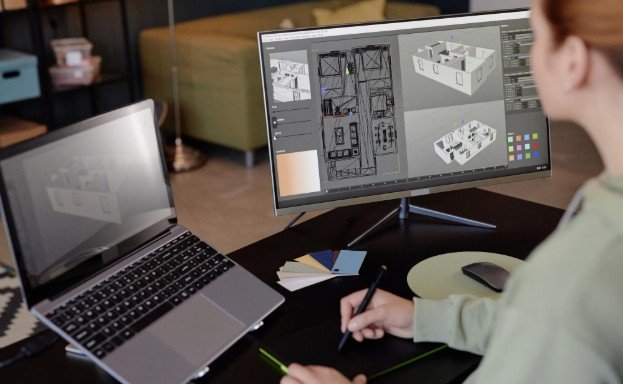
I would rather discover a misplaced curve on screen than after it becomes a ruined sheet of plywood. That is why I approach How to Prepare Architectural CAD Files for Digital Fabrication as a sequence of checks, rather than a final export command. A convincing architectural model can still contain geometry that a cutter, router, or printer cannot interpret correctly.
Good preparation connects design intent with material dimensions, machine capabilities, and assembly requirements. Whether you are producing façade panels, a terrain model, or an interior prototype, the following workflow helps prevent avoidable fabrication errors.
Confirm Workshop Requirements Before Editing
Start by identifying the fabrication process and requesting the receiving workshop’s specifications. For digital timber joinery, confirm tooling capabilities and joint tolerances. Ask about accepted formats, working dimensions, material restrictions, minimum features, and submission requirements.
Download its template when available. Layer colors, stroke widths, file versions, and operation names vary between workshops. Instructions suitable for one laser cutter may fail on another.
Confirm whether the operator wants individual parts or nested sheets. Some services arrange parts themselves; others expect a complete sheet layout. Establish these requirements before investing time in cleanup.
Set Units and Model Scale Correctly

Architectural drawings often describe full-size buildings, while fabrication files describe the physical parts being produced. Keep those two scales distinct.
For example, a six-meter façade becomes 60 millimeters wide in a 1:100 architectural model. Once reduced, its fabrication geometry should represent that 60-millimeter component at actual physical size.
Verify Dimensions After Export
Check a known dimension in both the working file and exported deliverable. Do not rely on visual appearance: a correctly shaped component can still arrive at the wrong size.
Record the units clearly. Confusion between inches and millimeters produces a 25.4-fold dimensional error. Avoid resizing again during printing or importing unless the workflow explicitly requires it.
Clean Geometry Without Losing Design Intent
Create a fabrication copy of your model so the original design remains editable. Remove title blocks, dimensions, hatching, reference images, and construction geometry that should not become machine operations.
Inspect hidden objects and overlapping curves. Duplicate lines can create repeated cuts, unnecessary machining time, or damaged edges.
Check Profiles and Surfaces
Close boundaries intended to define cutout parts or machining pockets. Keep intentional scoring paths open where appropriate.
For flat cutting, ensure geometry lies on the intended plane. For three-dimensional fabrication, inspect disconnected surfaces, invalid solids, and intersections.
Use cleanup tools carefully. Joining curves with an excessive tolerance can alter openings or erase details that matter during assembly.
Prepare Separate Files for Each Fabrication Process
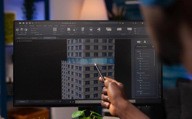
A coordinated architectural project may combine laser-cut walls, a routed base, and printed building details. Prepare each component according to its manufacturing method.
Laser Cutting: Organize Operations Clearly
Separate cutting, scoring, and engraving using the workshop’s conventions. Arrange components inside the permitted sheet boundary with the required margins.
Where supported, engrave first and cut internal openings before releasing outer profiles. This helps keep components positioned during processing.
Measure material thickness and test joints. Account for kerf, the width removed during cutting, but agree whether compensation belongs in your geometry or the operator’s software to avoid applying it twice.
CNC Routing: Design for Tool Access
A rotating cutter leaves a radius in internal corners. Where square mating parts must fit, consider approved corner reliefs or adjust the connection geometry.
Check pocket depths, narrow passages, and cutter reach. Include space for clamps and hold-down methods when arranging parts.
Confirm who prepares computer-aided manufacturing toolpaths. CAD geometry alone does not specify machining order, cutting tools, feeds, or machine instructions. The CAM stage must establish stock dimensions and a consistent work origin.
3D Printing: Check Solid and Mesh Integrity
Simplify architectural details that become too small at the chosen model scale. Thin railings, delicate screens, and tiny openings may require thickening or omission.
Check that printable bodies enclose valid volumes. Inspect holes, reversed faces, self-intersections, and unintended overlapping shells.
Export with suitable mesh resolution so curves remain smooth without unnecessarily large files. Confirm units explicitly when using STL, and review the model in the receiving software or slicer.
Check Assembly and Package the Deliverables
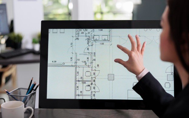
Assign consistent identifiers to components and use matching labels in an assembly reference. Verify that slots, locating features, and separately fabricated pieces align.
Test a representative joint before producing every part. A small prototype can reveal thickness variation or fit problems that screen checks miss.
Reopen every exported file and inspect dimensions, missing features, and unwanted geometry. Include material, measured thickness, quantities, units, revision information, and an assembly PDF where useful. Keep explanatory drawings separate from machine geometry.
Frequently Asked Questions
1. What is the first step in How to Prepare Architectural CAD Files for Digital Fabrication?
Confirm the fabrication method and obtain the workshop’s current template, accepted formats, and material requirements before preparing your export.
2. Which file format should I submit?
Use the workshop’s requested format. Vector cutting may accept DXF, DWG, or vector PDF; machining and printing requirements depend on the receiving workflow.
3. Should every fabrication profile be closed?
Close profiles defining parts or pockets. Scoring and engraving paths can remain open when the intended operation requires them.
Final Take
I treat a fabrication-ready file as a clear agreement between designer and workshop. Correct dimensions, clean geometry, and tested connections make that agreement dependable.
Before releasing a complete project, I would always reopen the exports and test its most demanding joint. Those checks turn an attractive digital design into components that can actually assemble as intended.