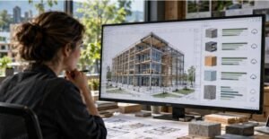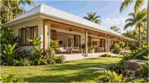
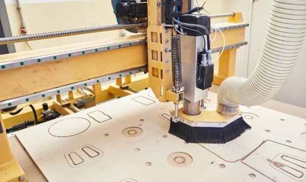
I have found that physical models expose design problems that can remain hidden on a screen. With CNC milling for architectural models, I can convert digital terrain, massing studies, façade concepts, and presentation designs into accurate physical pieces.
However, strong results require more than sending a three-dimensional file to a machine. Geometry preparation, material choice, toolpaths, tolerances, workholding, and finishing all influence whether the model looks precise or unfinished.
Why CNC Milling Works for Architectural Models
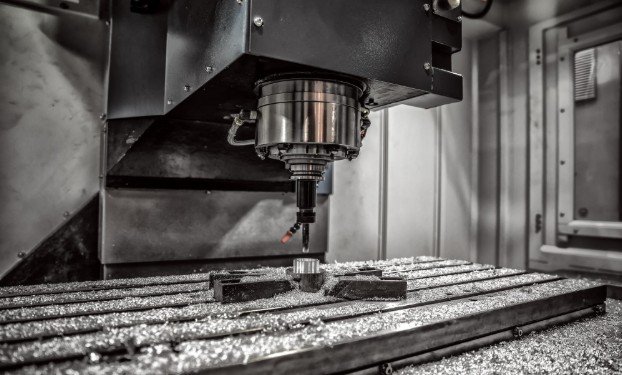
CNC milling is a subtractive process in which a rotating cutter removes material according to computer-generated instructions. It works particularly well for site contours, sloped terrain, landscape forms, building pads, large massing blocks, façade panels, and repeated components.
Compared with manual cutting, a CNC router can reproduce complex forms consistently and shape broad surfaces efficiently. It is especially valuable for topographic models that would otherwise require many stacked layers. The process also supports hybrid production, where milled terrain is combined with laser-cut buildings, 3D-printed details, and hand-finished landscape elements.
CNC Milling vs Laser Cutting and 3D Printing
Choose CNC milling for relief, thick panels, sculpted surfaces, terrain, and large components. Laser cutting is better suited to flat layers, delicate outlines, windows, and sheet assemblies. 3D printing works well for undercuts, enclosed forms, complicated joints, and small objects with complex geometry.
A hybrid workflow is often more effective than using one machine for every component. A milled site base can support laser-cut roads, printed buildings, transparent water features, and handmade vegetation. Selecting the fabrication method according to each component saves time and improves visual clarity.
Prepare the Digital Model Correctly

Establish the Final Scale
Set the final scale before creating toolpaths. At smaller scales, walls, steps, railings, and façade details may become thinner than the selected cutter or too fragile to survive machining.
Remove features that will not remain visible. Simplifying the model reduces machining time, prevents broken details, and directs attention toward the architectural ideas that matter.
Clean and Simplify the Geometry
Delete duplicate surfaces, hidden objects, unnecessary interiors, tiny details, and overlapping solids. Close open meshes and correct gaps, reversed faces, or disconnected geometry.
Buildings that will be manufactured separately should be removed from the terrain model and replaced with clean, level pads. This approach saves material and makes assembly easier.
Rhino, SketchUp, Revit, AutoCAD, and Fusion can support the workflow. STL is commonly used for terrain meshes, STEP and IGES preserve solid or surface geometry, and DXF works well for profiles, roads, boundaries, and engraved linework.
Follow a Reliable CAD-to-CNC Workflow
Define the Material Stock
Enter the exact length, width, and thickness of the material in the CAM software. Leave sufficient space around the model for clamps, screws, tabs, or another secure workholding method.
Select Suitable Cutters
Flat end mills are effective for clearing material, cutting pockets, shaping edges, and producing level building pads. Ball-nose end mills create smoother terrain and curved surfaces. V-bits can engrave roads, property boundaries, contour lines, and selected labels.
The cutter must be small enough to reproduce important details but strong enough to remove material safely. Using an unnecessarily small cutter can significantly increase machining time.
Plan Roughing and Finishing Passes
A roughing pass removes most excess material using deeper cuts and wider spacing. A finishing pass uses lighter cuts and a smaller stepover to improve detail and surface quality.
Trying to complete both operations in one aggressive pass can overload the cutter, increase vibration, and leave visible machining marks.
Simulate and Test the Toolpath
CAM simulation can expose collisions, unreachable areas, excessive cutting depth, and wasted movements before machining begins.
After reviewing the simulation, secure the stock, set the work origin accurately, confirm cutter length, and check spindle direction. An air cut or small material test can reveal setup errors before they damage the final piece.
Choose the Right Model-Making Material
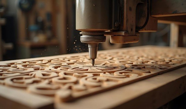
MDF is inexpensive, stable, and suitable for clean presentation bases. However, it produces fine dust and normally requires sealing before painting.
Plywood provides strength and attractive layered edges, although grain direction and alternating layers can affect fine details.
XPS and EPS foam are lightweight and fast to machine, making them practical for large terrain studies. Their softness can reduce edge sharpness. High-density urethane and tooling board offer smoother surfaces and finer detail but are generally more expensive.
Basswood and other fine-grained timbers suit premium models when cutter sharpness and grain direction are controlled. Acrylic and rigid PVC can produce precise features, but unsuitable feeds or excessive heat may cause melting.
Design Terrain, Roads, and Building Pads
Simplify terrain enough to reduce machining time without losing important landforms. Extremely tight contour intervals may create extensive tool movement with little visible improvement.
Roads can be engraved, recessed, applied as separate pieces, or represented through contrasting finishes. Building pads should be flat and include enough clearance for reliable fitting.
Tall buildings are usually better manufactured separately. Milling them directly into a terrain block wastes material, 3D printing techniques for cutter tools, and can make nearby surfaces difficult to finish.
Manage Scale, Radius, and Tolerance
Rotating cutters naturally produce rounded internal corners. A square digital pocket will not become perfectly square unless the design includes relieved corners or another suitable adjustment.
Components inserted into pockets need sufficient clearance for assembly, paint, sealant, and minor material movement. Minimum wall thickness must also reflect the chosen material. Narrow foam edges can crush, while thin timber elements may split along the grain.
Avoid Common Model-Making Mistakes
Frequent problems include designing features smaller than the cutter, selecting unsuitable material, retaining excessive detail, skipping the roughing pass, ignoring tool reach, choosing the wrong model scale, and securing the stock poorly.
Poor dust extraction can also affect visibility, surface quality, and machine performance. Applying parametric design and digital fabrication secrets effectively also depends on cutter inspection, secure workholding, proper guarding, efficient extraction, and clearly defined emergency procedures before every machining session.
Finish and Assemble the Model
Remove tabs and machining marks with suitable hand tools and progressively finer abrasives. Porous materials should be sealed before painting so the finish is absorbed evenly.
Dry-fit every component before permanent assembly. Contrasting buildings, translucent elements, engraved circulation routes, and carefully placed vegetation can make the final design easier to understand without overwhelming it with decoration.
Frequently Asked Questions
1. What is the best material for CNC milling for architectural models?
MDF is suitable for stable presentation bases, foam works well for large terrain studies, and tooling board provides sharper professional details. The right choice depends on scale, budget, durability, and the required finish.
2. Can a CNC router produce detailed buildings?
Yes, but cutter diameter, tool reach, internal corner radius, material strength, and model scale determine the smallest possible details. Complex buildings are often easier to manufacture separately.
3. Which file format should be used?
STL is common for terrain meshes, STEP and IGES preserve solid or surface geometry, and DXF works well for profiles and engraved lines. The best option depends on the CAM software and model geometry.
4. Is CNC milling better than 3D printing?
Neither method is universally better. Milling is often faster for terrain and broad surfaces, while 3D printing handles undercuts, enclosed forms, and intricate geometry more effectively.
Final Perspective
I see CNC model making as part of the design process rather than merely a final production step. When I simplify geometry intelligently, match the cutter to the material, simulate each toolpath, and plan assembly from the beginning, the physical model becomes more accurate and easier to interpret.
The strongest results come from balancing digital precision with practical craftsmanship. Instead of reproducing every detail, I focus on the features that communicate scale, terrain, circulation, massing, and architectural intent most clearly.