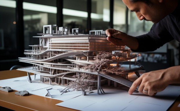
A joint that looks flawless on screen can become the part that stops an entire installation. I find this gap between digital certainty and physical assembly especially important when reviewing architectural details.
Fabrication Tolerances in Architecture determine how much a manufactured component may vary while still meeting its intended requirements. Understanding them helps designers create connections that fit, accommodate realistic variation, and preserve architectural quality without demanding unnecessary precision.
What Does Fabrication Tolerance Actually Mean?
Fabrication tolerance is the permissible variation from a specified dimension or geometric requirement. A panel designed at 1,000 millimeters with a length tolerance of ±2 millimeters may measure between 998 and 1,002 millimeters.
That allowance does not automatically guarantee successful assembly. Designers must also consider position, flatness, straightness, and the relationship between adjoining components.
Tolerance, Clearance, and Kerf Are Different
Tolerance describes allowable variation. Clearance is the intentional space between mating parts. Kerf is the width of material removed during cutting.
Movement allowance serves another purpose: accommodating changes after installation, including thermal expansion, moisture movement, or structural deflection. Treating these terms as interchangeable can produce joints that fit initially but fail later.
Why Can Acceptable Components Still Fail to Fit?
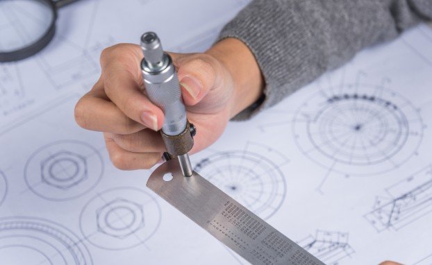
A component can meet its individual requirements and still clash with another acceptable component. The problem often occurs where different trades, materials, and measurement systems meet.
A accurately manufactured façade panel, for example, must connect to a structure whose actual geometry may differ from the design model. Factory precision cannot remove that interface mismatch.
Understand Accumulated Variation
Consider a simplified assembly with three independent dimensional contributions, each permitted to vary by ±2 millimeters. If their effects align in the same direction, the worst-case combined variation reaches ±6 millimeters.
This illustrative calculation assumes a direct dimensional chain. Real assemblies require signed dimensions, defined reference points, and consideration of adjustment capacity. Statistical calculations need justified process data rather than assumptions that errors will conveniently cancel.
How Do Materials and Machines Affect Accuracy?
Different fabrication processes produce different patterns of variation. Specifying the same tolerance across every material and machine rarely makes sense.
Timber, Metal, and Printed Components
Timber dimensions respond to moisture content, grain direction, and conditioning. Measure actual sheet thickness before designing interlocking plywood joints.
Metal components may change through bending, welding distortion, and temperature variation. Printed components can exhibit shrinkage, warping, and differences between build directions.
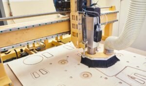
CNC routing introduces tool diameter, deflection, and wear. Laser cutting requires attention to kerf and edge taper. These effects should inform compensation and testing, rather than become excuses for uncontrolled results.
How Should Architects Specify Critical Dimensions?

Start with function. Identify which dimensions affect structural connections, sealing, alignment, replaceability, and assembly access. Reserve tighter requirements for features where variation has meaningful consequences.
Each critical requirement should state the nominal dimension, allowable deviation, reference datum, and inspection method. A datum provides the agreed reference point, line, or plane from which measurements are taken.
Separate manufacturing requirements from installation requirements. A correctly sized panel can still sit in the wrong position.
Where relevant standards apply, confirm the appropriate edition and component scope. Communicate additional requirements before pricing and production so fabricators can assess feasibility and cost.
How Can Digital Models Support Reliable Assembly?
Detailed geometry does not prove dimensional accuracy. A model can contain every fastener while relying on an incorrect opening size or outdated survey. Before you prepare architectural CAD files for digital fabrication, verify critical dimensions against current site measurements and approved project information.
Use verified coordinates and maintain consistent units across CAD, BIM, and CAM transfers. Organize repeated components into controlled types, with identifiable parts and clear revision records.
Review tool access, assembly sequence, transportation limits, and connection access before releasing production files. Repeatability improves production only when the underlying detail works.
Traceability also matters: teams should know which approved model, drawing, and revision produced each component.
Which Details Accommodate Realistic Variation?
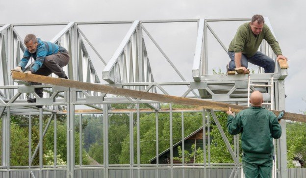
Adjustment should be designed into the connection. Depending on the engineered system, suitable options may include adjustable brackets, approved slotted holes, shims, and deliberately dimensioned joints.
These provisions must maintain load transfer, edge distances, weather resistance, and the intended appearance. An oversized gap is not automatically a workable solution.
Survey critical interfaces before fabrication when their actual dimensions influence production. Compare the measured structure against the design and resolve significant discrepancies early.
Test representative joints using the specified material, machine, and settings. For visible or performance-critical assemblies, use a mock-up to check fit, alignment, installation access, and finishing.
Frequently Asked Questions
1. Why Are Fabrication Tolerances in Architecture Important?
They define acceptable manufacturing variation and help coordinate components into buildable assemblies. Combined with appropriate clearances and installation provisions, they reduce unexpected clashes and protect performance.
2. Are Tighter Tolerances Always Better?
No. Unnecessary precision can increase machining time, inspection effort, and rejected material. Requirements should reflect the function of each feature and the capabilities of the selected process.
3. Can BIM Clash Detection Replace Tolerance Analysis?
No. Conventional clash checks typically evaluate modeled geometry. Tolerance analysis examines the variation that manufacturing and installation may introduce around that geometry.
4. When Should Prototype Testing Happen?
Test before final production, particularly for unfamiliar materials, new machine settings, repeated joints, or details with limited adjustment. Repeat checks when important production conditions change.
A Better Fit Starts Before Production
I would rather resolve a difficult interface in a drawing review than leave installers to improvise around it. Reliable assembly begins with realistic requirements, verified dimensions, and connections that accommodate expected variation.
By testing critical details and recording decisions clearly, I can judge whether a design is ready to become a physical building.