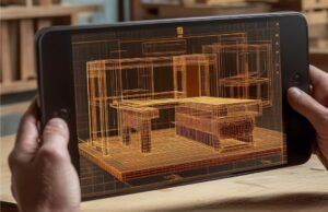
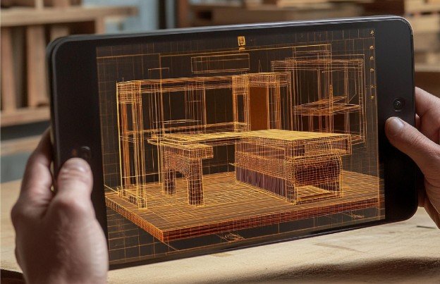
I find a timber connection most interesting when its shape explains how it works. A fitted shoulder carries weight, a dovetail resists separation, and a wooden peg keeps adjoining members together. Digital timber joinery brings these principles into a workflow where computer models guide fabrication.
Its appeal goes beyond hiding hardware: designers can coordinate geometry, machining, and assembly before cutting wood. However, precision alone cannot guarantee strength. Successful connections must also accommodate grain direction, moisture changes, and the loads they will carry.
What Makes Timber Joinery Digital?
The process starts with a digital model that defines how wooden components meet. Computer-aided manufacturing software translates the geometry into toolpaths, which guide a CNC machine or robotic milling system.
Traditional craftsmanship still informs the connection. Technology helps reproduce complex shapes and coordinate variations across multiple components.
Metal-free, concealed-hardware, and adhesive-free construction mean different things. A connection can hide steel plates while still depending on them. An all-wood joint may use wooden pegs or wedges, while engineered timber members can contain adhesives within their manufactured layers.
How Do Wood Connections Hold Without Metal?
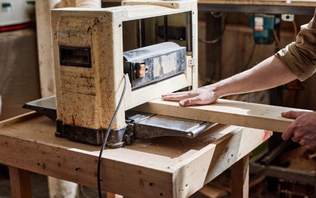
Joint geometry determines how forces travel between members. Contact surfaces transfer compression, while interlocking shapes restrict movement. When using digital fabrication with recycled materials, joint design must account for variations in material thickness and condition. Pegs, wedges, or wooden keys can provide additional restraint.
The remaining timber matters as much as the cut. Removing material creates the connection but reduces the member’s cross-section. Designers must evaluate both the joint and the surrounding wood.
Mortise-and-Tenon Connections
A projecting tenon fits inside a matching mortise. Shoulders provide bearing surfaces, while a wooden peg or wedge can restrain withdrawal. Proportions, grain orientation, and edge distances influence performance.
Dovetails and Interlocking Connections
A dovetail’s widening profile resists separation in particular directions. It can connect frames or panels, but its performance depends on the load direction and surrounding material.
Lap Joints and Japanese-Inspired Geometry
Lap joints overlap members through matching recesses. Adapted Japanese connections can introduce more elaborate locking geometry. Digital fabrication makes repetition easier, although machining access and assembly direction may require changes to traditional shapes.
From Digital Model to Finished Assembly
For architects, digital timber joinery works best when fabrication constraints enter the design early. A connection that looks elegant onscreen may be impossible to cut or assemble.
Model the Material and Connection
Define actual member dimensions, joint depth, grain direction, and intended loads. Parametric models can update related dimensions together, but automatically generated geometry still needs review.
Check Machine Access
Three-axis CNC machines can produce many adapted joints, provided tools can reach the required surfaces. Other geometries require repositioning, additional setups, or machines with more axes.
Rotating cutters leave rounded internal corners. Designers must accommodate the tool radius through matching geometry, relief cuts, or secondary finishing.
Prototype Before Production
Machine a sample using representative material. Check fit, bearing contact, insertion direction, and assembly force. Revise the model before producing the full batch.
Plan Assembly and Identification
Determine which component enters first and how later pieces lock it in place. Part labels, orientation marks, and clear drawings help translate the model into construction instructions.
Why Tolerances and Moisture Matter
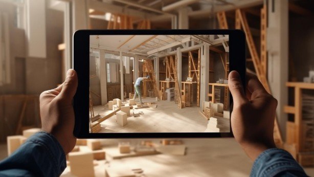
A joint needs enough clearance to assemble without damaging its edges. Excessive clearance, however, can introduce unwanted movement or prevent intended surfaces from engaging.
There is no universal clearance suitable for every project. Species, moisture content, cutter condition, machine accuracy, and connection geometry all affect fit.
One recent reconfigurable wall prototype used a calibrated 0.25-millimeter clearance and underwent repeated assembly cycles without screws, nails, or adhesives. That figure describes its particular setup; it is not a default specification.
Wood also changes dimensions with moisture, particularly across the grain. Fabrication and installation conditions must therefore inform connection design.
What Real Projects Demonstrate
The Watari-ago Shelter demonstrates how a traditional Japanese connection can be adapted for three-axis CNC fabrication. Its full-scale construction connects digital modeling with practical timber assembly.
Research into reconfigurable walls extends this approach by coordinating joint geometry, robotic milling, and augmented-reality instructions.
Digital joint libraries provide another starting point, offering downloadable geometries and assembly diagrams. These resources support experimentation, but downloadable files should not be treated as verified structural designs.
Benefits and Limits Worth Understanding
All-wood connections can express craftsmanship and support disassembly when their geometry and locking elements permit removal. Reusable components may reduce replacement demand.
However, machining time, material removal, specialized modeling, and trial fitting can increase costs. Metal-free construction is not automatically cheaper or environmentally superior.
Structural applications require engineering assessment, including connection strength, stability, moisture exposure, and applicable fire requirements.
Frequently Asked Questions
1. Does digital timber joinery require glue?
Some systems use interlocking geometry, wooden pegs, or wedges without glue. Others need adhesives. The connection design determines what is required.
2. Can a Three-Axis CNC Machine Cut Every Joint?
No. Tool access, cutting depth, and internal geometry limit what it can produce.
3. Can These Connections Be Dismantled?
Some can. Reversibility depends on assembly direction, access to locking elements, and whether components remain removable after installation.
My Final Take
I see the greatest value in designing the connection and fabrication process together. Beautiful geometry matters, but accessible cuts, dependable fit, and sensible assembly make it useful.
I would begin with a representative prototype, refine the tolerances, and seek engineering input before scaling up. That approach preserves the appeal of all-wood construction while giving practical performance equal attention.