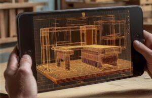

A model can look complete while leaving the workshop with unanswered questions. Where does the drill enter? Which connection needs clearance? Has this panel changed since approval? I approach BIM to Fabrication: Turning Building Models Into Production Files by answering those questions before discussing export buttons.
Reliable production starts when designers and fabricators agree on what each component requires, how its information travels, and who authorizes manufacturing.
What Makes a Building Model Ready for Fabrication?
An architectural model communicates building layout, dimensions, and design intent. A fabrication model adds the information needed to manufacture specific components, including connections, material specifications, machining operations, and assembly relationships.
For example, a timber beam shown at the correct size may still lack joint geometry, drilling directions, or machining allowances. A steel member may need holes, copes, weld details, and identification marks before production.
Fabrication readiness therefore depends on the intended process. A detailed model or an LOD 400 label alone does not prove that a particular machine can manufacture its components.
How Do Building Models Become Production Files?

Agree on Requirements Before Detailing
Start with the fabricator’s equipment, software, accepted formats, and approval process. Establish units, coordinates, material specifications, component naming, and dimensional tolerances.
Confirm whether the workshop needs individual parts, complete assemblies, panel data, or cutting layouts. Record who checks geometry, who prepares manufacturing data, and who releases files. Early agreement prevents detailed modeling that produces unusable outputs.
Develop the Manufacturing Geometry
Convert design elements into components that reflect how they will be made and assembled. Add connection details, offsets, clearances, and material thicknesses where relevant.
For folded sheet metal, account for bend allowances using appropriate manufacturing tools. For timber, define joints and machining operations supported by the selected export workflow. For steel, resolve connections and part marks.
Consider stock sizes, tool access, handling, transport, and installation. A component that fits digitally can still be impractical to manufacture or deliver.
Generate Documentation and Machine Data
Create shop drawings, bills of materials, cut lists, and assembly information from the approved fabrication model wherever the workflow supports it. Clearly document fabrication tolerances in architecture so manufacturers and installers understand acceptable dimensional variations and required fit between components.
Some systems export manufacturing data directly. Others transfer geometry into specialist fabrication or CAM software, where operators define machining strategies and generate machine instructions.
Keep this distinction clear: an exported shape is not automatically a validated toolpath.
Which File Formats Does the Workshop Need?
The right format depends on the trade and receiving system. IFC can support model exchange and coordination, but acceptance for manufacturing requires checking the information preserved by that specific workflow.
DXF often carries two-dimensional profiles or drawing geometry. It may still require cleanup, nesting, and CAM processing before cutting.
Steel workflows can use DSTV/NC files for supported fabrication operations. Timber workflows may use BTL or equipment-specific formats. Their capabilities differ, so verify supported objects and operations with the fabricator.
PDF drawings remain useful for dimensions, assembly instructions, and inspection. Bills of materials and cut lists complement machine data rather than replacing it.
How Should Production Files Be Checked?

Validate Geometry and Export Settings
Check scale, units, orientation, coordinates, component quantities, and material assignments after export. Confirm that holes, cuts, and connections survive the transfer.
Open files in the receiving application or an appropriate viewer. Compare critical dimensions against the approved model and shop drawings. Inspect mirrored components and unusual geometry particularly carefully.
Confirm Machine Compatibility
Check the selected machine configuration and, where applicable, CAM postprocessor. Review tooling, cutting direction, workholding, and operation sequences with the production team.
Run simulation or other supported verification before release. For unfamiliar details, agree on a prototype or first-piece inspection. Successful export confirms that a file was created; workshop verification establishes whether it is usable.
How Do Revisions Stay Connected to Production?
Give each component a stable identifier linking its model object, drawing, material record, and production file. Add revision information without losing that identity.
When the design changes, identify affected parts, regenerate relevant outputs, and withdraw superseded files. Check whether earlier components have already been cut, ordered, or shipped.
A shared information environment helps teams track approval and release status. However, document approval and machine verification serve different purposes. Maintain both, and make the current production package easy for operators to identify.
Frequently Asked Questions
1. What does BIM to Fabrication: Turning Building Models Into Production Files involve?
It involves adding manufacturing information to building models, producing the required documentation and machine data, checking compatibility, and releasing approved outputs to the workshop.
2. Can a Revit model go directly to a CNC machine?
Some integrated workflows support production exports, but many require specialist detailing or CAM software. The route depends on the component, available integration, and machine requirements.
3. Does every fabricator need the same files?
No. A steel workshop, timber factory, and sheet-metal contractor may require different formats and information. Agree on deliverables before modeling production details.
4. Why are shop drawings still useful?
They support human review, assembly, and inspection. They also help teams compare intended dimensions and connections with exported manufacturing data.
My Final Take
I see a dependable fabrication workflow as a sequence of accountable decisions. Define the workshop’s requirements, develop manufacturable components, validate the outputs, and control every release.
I would rather resolve an unclear connection during review than discover it after cutting. When the model, documentation, and production files share consistent identifiers and revisions, teams can carry design intent into manufacturing with greater confidence.