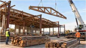
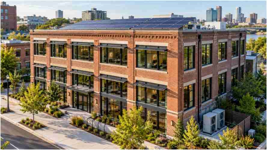
I have watched too many retrofit projects hemorrhage capital because the engineering team bought massive heat pumps first. If you replace mechanical equipment before fixing the envelope, you lock in oversized compressors, frequent cycling, and inflated utility bills. Proven net zero energy building retrofitting methodologies do the opposite.
They demand a disciplined, phased approach: isolate the thermal boundary first, slash conditioning demand second, electrify mechanical systems third, and balance remaining loads with on-site renewables last.
Over 85% of existing structures must reach zero-emission readiness to hit benchmarks tracked by the International Energy Agency (IEA). Tearing down these assets wastes immense embodied carbon.
The Core Principle: Demand Reduction Dictates Plant Sizing
My engineering team uses a non-negotiable rule on every commercial site: the building envelope sets the plant size. When you tighten the perimeter and eliminate thermal bridging, heating and cooling demands plummet by 30% to 50%. That reduction cuts thousands of dollars from your mechanical budget before you issue a single HVAC equipment purchase order.
+————————————————————-+
| PHASED INTERVENTION HIERARCHY |
| |
| [Diagnostics & BIM] ──► [Continuous Envelope] |
| │ |
| ▼ |
| [Net-Zero PV Offset] ◄── [Right-Sized Electrified MEP] |
+————————————————————-+
Step 1: Calibrated Baseline Diagnostics Over Guesswork
I never accept historic monthly utility bills at face value. They mask underlying issues like baseload spikes, simultaneous heating and cooling, and night-setback failures.
We begin by pulling 15-minute smart meter interval data and internal sub-meter logs into an energy analytics engine. Next, we build a calibrated 3D digital twin in Autodesk Revit and simulate thermodynamic loads through EnergyPlus, following the diagnostic guidelines established by the U.S. Department of Energy (DOE) Building Technologies Office.
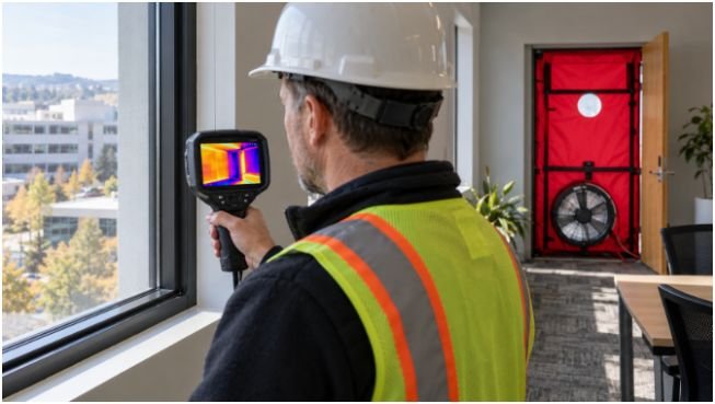
Before drafting the scope of work, we conduct on-site physical forensics:
- Multi-point blower door depressurization testing to measure baseline air infiltration (ACH50).
- Infrared thermography during a high indoor-to-outdoor temperature differential ($\Delta T \ge 15^\circ\text{C}$) to pinpoint concealed thermal bridging at floor slabs and parapets.
- Smoke-pencil isolation around fenestration perimeters and curtain-wall spandrels.
Step 2: The Continuous Envelope Boundary
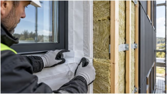
Once we locate envelope failures, we seal the conditioned boundary without interruption. We apply vapor-permeable airtightness membranes coupled with high-adhesion acrylic flashing tapes along every structural joint and window-to-wall interface. Our field standard requires achieving 1.0 ACH50. If a building fails that benchmark during mid-phase testing, we halt mechanical procurement immediately until the air barrier passes.
Next comes continuous insulation. Adding interior or exterior mineral wool panels disrupts direct conductance through concrete framing and steel studs. Where architectural covenants permit, exterior insulation finish systems (EIFS) or rainscreens keep the structural mass inside the thermal envelope, mimicking the thermal mass benefits seen in historical energy reduction in vernacular construction.
For fenestration, we replace failing aluminum-frame windows with spectrally selective, argon-filled triple glazing or vacuum-insulated glass (VIG) paired with exterior automated louvers.
Active MEP Modernization: Right-Sizing Mechanical Systems
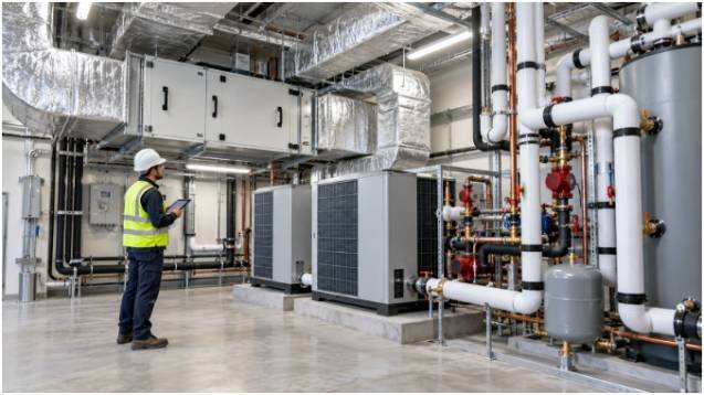
Only after the thermal boundary passes inspection do we touch the mechanical plant. With heat loss through air exchange and conductance minimized, standard heating and cooling rules of thumb no longer apply.
LEGACY TRADEOFF NZEB RETROFIT
┌───────────────────────────┐ ┌───────────────────────────┐
│ Leaky Envelope │ │ Airtight Boundary │
│ ACH50 > 5.0 │ │ ACH50 ≤ 1.0 │
│ │ │ │ │ │
│ ▼ │ │ ▼ │
│ 100-Ton Boiler/Chiller │ │ 45-Ton Variable Heat │
│ Oversized & Cycling │ │ Pump + MVHR (90% Eff.) │
└───────────────────────────┘ └───────────────────────────┘
Balanced Mechanical Ventilation with Heat Recovery (MVHR)
A sealed building traps moisture, volatile organic compounds, and carbon dioxide. Installing high-efficiency Mechanical Ventilation with Heat Recovery (MVHR) systems solves this problem.
Modern counterflow heat exchangers recover between 85% and 93% of sensible and latent heat from outgoing exhaust air, transferring it into the incoming fresh air stream without cross-contamination. We program these systems to modulate based on real-time indoor air quality metrics, ensuring indoor carbon dioxide levels remain strictly below 800 ppm during peak operational hours.
Heat Pump Electrification and Thermal Loops
We rip out legacy gas-fired atmospheric boilers and open-loop cooling towers. In their place, we install Air Source Heat Pumps (ASHPs) or Ground Source Heat Pumps (GSHPs) engineered to supply low-temperature hydronic fan coils or variable refrigerant flow (VRF) terminal units.
Because the envelope upgrades lowered peak loads, we routinely downsize heating equipment nameplate capacity by 40% to 60% compared to original design drawings. These systems run at seasonal coefficients of performance (COP) exceeding 3.5, complying with commercial efficiency targets under ASHRAE Standard 90.1.
Algorithmic Decision-Making: NSGA-III and TOPSIS in Practice
Retrofit decisions quickly run into conflicting variables. Thick insulation prevents winter heat loss, but excessive insulation can trap internal heat and cause summer overheating. Choosing the optimal combination requires computational multi-objective optimization rather than intuition.
OPTIMIZATION PIPELINE
[ Building Envelope & Future Climate Models ]
│
▼
[ NSGA-III Genetic Algorithm Optimization ]
* Objective A: Minimize Energy Use Intensity (EUI)
* Objective B: Minimize Capital Expenditure ($)
* Objective C: Minimize Thermal Discomfort (PPD)
│
▼
[ Non-Dominated Pareto Front ]
│
▼
[ TOPSIS Multi-Criteria Decision Ranking ]
│
▼
Selected Capital Retrofit Package
In a recent institutional project, our team linked EnergyPlus simulations to a Non-Dominated Sorting Genetic Algorithm (NSGA-III). The algorithm evaluated thousands of component combinations across three competing objectives:
- Minimizing annual Energy Use Intensity (kWh/m2/year).
- Minimizing upfront capital investment.
- Minimizing occupant thermal dissatisfaction, measured by the Predicted Percentage of Dissatisfied (PPD) index.
The optimization output produced a non-dominated Pareto front of fifty valid design configurations. To choose the winning package, we ran the dataset through a Technique for Order Preference by Similarity to Ideal Solution (TOPSIS) model. TOPSIS ranks options by their geometric distance from a hypothetical ideal solution and the worst-case negative ideal.
This mathematical framework revealed that spending an extra $24,000 on window solar heat gain coefficient (SHGC) coatings reduced lifetime chiller operational expenses by $118,000, an insight standard single-variable payback equations missed entirely.
On-Site Generation and Future-Proofing for 2050
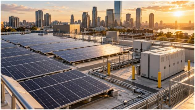
The final step is balancing remaining energy demand with on-site generation. We model solar photovoltaic arrays using irradiance datasets from the National Renewable Energy Laboratory (NREL), tailoring rack angles directly to site latitude. In northern climates, we set panels between 45° and 60° to capture low-altitude winter sun and shed heavy snow loads.
We also integrate behind-the-meter Lithium Iron Phosphate (LFP) Battery Energy Storage Systems (BESS). The battery bank absorbs surplus afternoon solar generation and discharges during evening grid peak rates, protecting the property against time-of-use utility charges.
Typical Historical Retrofit Design:
[Historical TMY Weather Data] ──► Baseline Envelope ──► High Risk of Summer Performance Drift
Resilient NZEB Design:
[Projected 2050 IPCC Warming Models] ──► +35% Insulation & +50% PV Capacity ──► Stable Net-Zero Balance
Designing retrofits using historical Typical Meteorological Year (TMY) weather data leaves buildings vulnerable to future climate shifts. Rising summer temperatures drive cooling loads up over a 30-year operational lifecycle.
In our models, maintaining a true net-zero balance across decades requires designing envelopes with up to 35% higher thermal insulation values and sizing renewable generation arrays 50% larger than historical utility records recommend.
Stop Over-Engineering Bad Envelopes
If your retrofitting strategy begins with equipment catalogues rather than blower doors and thermal imaging cameras, step back and re-evaluate. Decarbonization is a physics problem, not an equipment shopping spree.
Audit your utility interval logs, commission a blower door test, and seal the building envelope before you replace a single chiller. Cutting thermal and air leakage loads first shrinks your equipment footprints, slashes capital costs, and ensures your path to net-zero performance remains durable for decades.
Applying modern circular principles like building deconstruction preserves structural steel and masonry, leaving the core intact for a deep performance overhaul.
Frequently Asked Questions
1. What are net zero energy building retrofitting methodologies?
They are systematic, phased renovation workflows that reduce building thermal demand, electrify mechanical systems, and generate the balance on-site with renewables.
2. Why must envelope sealing precede heat pump installations?
Airtight sealing lowers conditioning loads by up to 50%, preventing the costly purchase and inefficient cycling of oversized heat pumps.
3. What role does NSGA-III play in building retrofits?
NSGA-III is an evolutionary optimization algorithm that balances competing trade-offs between energy consumption, equipment costs, and occupant comfort.
4. How much additional solar capacity is needed for future climate adaptation?
Long-term thermodynamic projections indicate retrofit solar arrays must be sized up to 50% larger to offset rising summer cooling loads by 2050.